


(An article to benefit NHAI EPC/HAM contractors, major design consultants, state PWD highway programs. By Dr Sanjay Rana, sanjay@parsan.biz)
Linear infrastructure- highways, railways, metros, canals, transmission corridors, pipelines- fails or gets delayed for one core reason: the subsurface is variable, but the alignment is treated as uniform. A “corridor geophysics” package is a practical, scalable way to reduce that uncertainty before and during construction by creating a continuous ground model along the alignment and then confirming only the critical locations with targeted boreholes. The result is a measurable reduction in redesign, claims, delays, over-excavation, and surprise ground conditions.
Why alignment risk persists
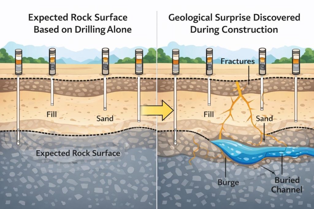
Traditional site investigation often relies on widely spaced boreholes. Boreholes are excellent at what they do, but they are point measurements. Between two boreholes, the ground can change drastically- soft pockets, buried channels, collapsible fills, bouldery zones, clay lenses, perched water, shallow rock highs/lows, old utilities, voids, abandoned foundations, karstic cavities, or highly weathered rock bands. These are exactly the features that cause settlement, pavement distress, embankment instability, foundation issues for bridges/RE walls, and costly change orders.
A corridor geophysics approach addresses this gap by adding continuous or high-density profiling so that risk is mapped between boreholes and not discovered during excavation.
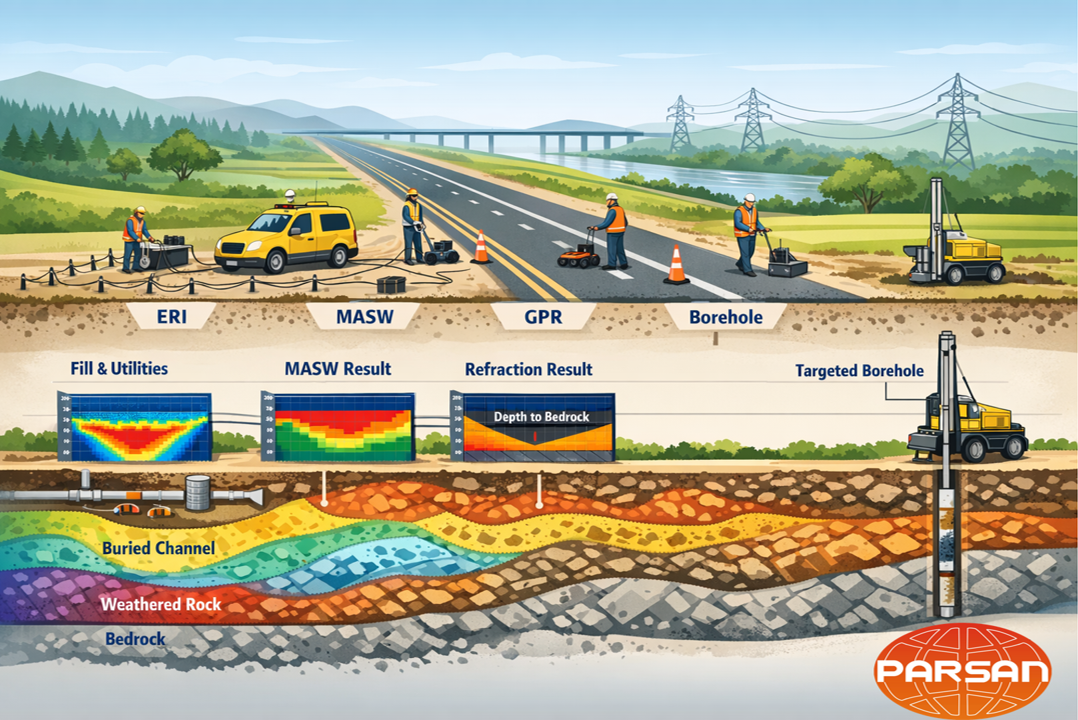
What a “Corridor Geophysics” package includes
1) ERI (Electrical Resistivity Imaging): the hydro–lithology risk mapper
ERI is the workhorse for corridor-scale risk because it detects lateral and vertical changes tied to moisture, clay content, weathering, fractures, seepage pathways, and void-prone zones. In alignment work, ERI is especially effective for:
- Identifying soft/weak zones, saturated pockets, and clay-rich stretches
- Locating buried paleo-channels and variable alluvium thickness
- Mapping weathered rock profiles and fracture zones
- Flagging potential voids/cavities in appropriate geological settings
- Supporting slope/embankment stability screening in hilly terrain
ERI does not “replace” drilling; it tells you where drilling must be concentrated.
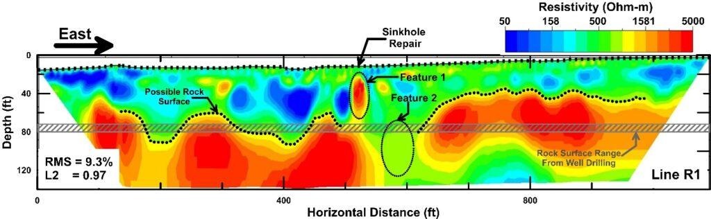
Example electrical resistivity imaging (ERI) section from a geophysics-integrated highway investigation, showing interpreted rock surface and subsurface anomalies. Source: Fast Times Online (adapted from Integrating Geophysics into Geotechnical Investigations Along Alabama Highways).
2) MASW: stiffness profiling for settlement and pavement performance
MASW provides a continuous view of shear-wave velocity (Vs), which correlates strongly with stiffness and settlement behaviour. For highways and railways, MASW is valuable because it directly supports:
- Subgrade stiffness zoning for pavement/formation design
- Detecting low-stiffness pockets that become future rutting/settlement zones
- Optimizing ground improvement extents (lime/cement stabilization, stone columns, geogrids)
- Rapid, non-intrusive coverage over long distances
In corridor terms: MASW turns “unknown variability” into a stiffness map you can design against.
3) Seismic Refraction: depth to bedrock and rock quality contrasts
Seismic refraction is a fast method to estimate P-wave velocity and map the rockhead geometry, rippability trends, and velocity contrasts that signal weathering or competent rock. Along corridors it helps:
- Determine depth to bedrock and bedrock undulations
- Identify highly weathered zones and low-velocity bands that may correlate with weak rock
- Improve earthwork planning: cutting, blasting needs, and transition zones
- Reduce surprises in bridge approaches, retaining wall foundations, and cut slopes
When integrated with MASW/ERI, refraction strengthens confidence in the rockhead interpretation.
4) GPR: shallow “high-resolution” scanner where it matters
GPR is not used everywhere blindly; it is used where high-resolution shallow imaging is decisive:
- Existing road widening: utilities, ducts, rebar, pavement layer thickness
- Detecting shallow voids, poor compaction zones, and anomalous backfill (site dependent)
- Bridge deck/approach slabs, drain locations, and concrete layer interfaces
- Urban corridors where “unknown services” are the biggest construction risk
GPR provides the detail that other methods cannot at shallow depths- particularly in dry to moderately conductive ground.
5) Targeted boreholes: verification, sampling, and design-grade parameters
The “corridor package” is completed by targeted drilling, not blanket drilling. Boreholes are placed:
- At anomaly zones detected by geophysics
- At transitions (high Vs to low Vs, resistive to conductive, rockhead step changes)
- At critical structures (bridges, RE walls, flyovers, culverts, tunnels/shafts)
- At representative “good” zones for benchmarking
This strategy typically improves value because drilling becomes purposeful, and geophysics becomes actionable, not just interpretive.
How the package reduces alignment risk (in practical terms)
1) Fewer surprises = fewer redesigns
When the ground model is continuous, design teams see risk early: weak pockets, deep alluvium, rockhead lows, saturated stretches. This enables proactive decisions- change foundation type, adjust embankment treatment, modify drainage, or refine the alignment micro-profile.
2) Optimized ground improvement quantities
Many projects overspend on stabilization because variability is not mapped. Corridor geophysics supports zonal treatment– treat where required, not everywhere.
3) Better construction planning and scheduling
Refraction-informed rippability and rockhead geometry improves excavation planning. ERI highlights wet zones and seepage risk that may demand dewatering or drainage measures. The contractor avoids the “discover and react” cycle.
4) Stronger claim defensibility (and fewer disputes)
Disputes often arise from “unforeseen ground conditions.” A corridor geophysics + verification drilling approach creates a documented baseline, reducing ambiguity.
A recommended workflow for implementation
- Desk study & risk hypothesis
Geology, geomorphology, drainage, land use, previous bore logs, known utilities, and failure history along similar corridors. - Reconnaissance surveys & method selection
Choose the mix (ERI/MASW/refraction/GPR) and spacing based on terrain, expected depth, ground conductivity, and project stage. - Production surveying along the alignment
Continuous profiling wherever practical; denser coverage at structures and suspected risk zones. - Integrated interpretation and corridor zoning
Deliverables should be risk-based, not just method-based:
- Rockhead undulation zones
- Low-stiffness zones
- Saturation/soft ground zones
- Utility conflict zones
- Transition zones (often most problematic)
- Targeted boreholes and ground-truth updates
Verify anomalies; update the model; convert it into design inputs. - Design integration & construction support
Use the corridor model to finalize investigation scope for detailed design and to guide QA/QC during execution.
What “good deliverables” look like
A corridor geophysics package should not end as four separate reports. The final output should be a unified alignment product:
- Corridor Risk Zonation Map (chainage-based)
- Integrated long-section with interpreted layers/rockhead and key anomalies
- Structure-wise investigation recommendations
- Borehole targeting plan with rationale linked to anomalies
- Design-relevant parameters where appropriate (Vs ranges, depth to competent strata trends, variability zones)
The real message: geophysics is the alignment intelligence layer
For corridor projects, the goal is not to “do ERI” or “do MASW.” The goal is to build alignment intelligence– a continuous understanding of the subsurface that prevents costly surprises. With ERI + MASW + refraction + targeted GPR, and boreholes used as verification rather than blind spacing, the project moves from reactive problem-solving to proactive risk management. That is the simplest, most scalable way to reduce alignment risk- without inflating investigation time or budgets.
.jpg)