

PARSAN- Geophysics Service Providers in India, Singapore, Kingdom of Saudi Arabia and Bahrain!
Non-invasive Subsurface Investigation Specialists
PARSAN, an ISO 9001-2015 company, is established as a pioneer in applied near-surface geophysics in India, providing Contracting and Consulting services to clients from the Geotechnical, Civil Engineering, Mineral, Hydrological and Environmental industries. With offices now in the Kingdom of Saudi Arabia, Kingdom of Bahrain, and Singapore, PARSAN continues to expand its reach and deliver high-quality solutions globally. The company owns the largest range of near-surface geophysical survey equipment in Indian private sector and continues to expand its resources to advance their geophysical survey capability.
What inspires our specialists is the idea of providing all of our clients with the widest range of solutions adapted to their needs in order to deliver the best data available in today's market.
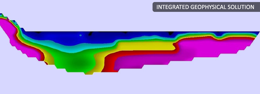
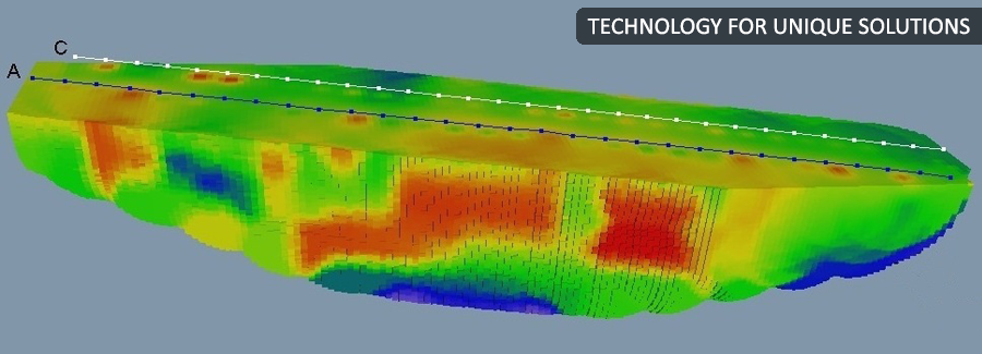
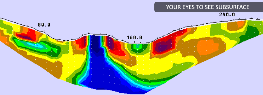
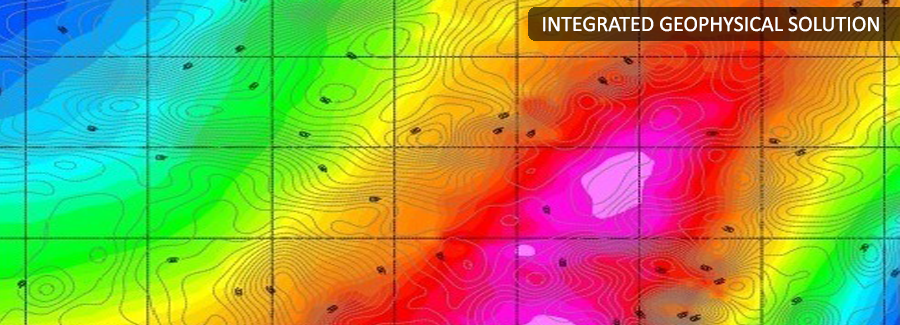
It’s an established fact that a single geophysical technique can’t provide a unique solution to subsurface problems. PARSAN has a wide range of geophysical tools at its disposal, and vast experience to suggest its clients the right combination of tools to be used to address to subsurface investigation challenges. PARSAN strives to use technology for providing unique solution.
PARSAN has work experience in India, Singapore, Oman, Afghanistan, Bahrain, Kuwait, Kingdom of Saudi Arabia, Bhutan, Bangladesh and Nepal. The company has Offices in Delhi, Kolkata, Bahrain, Kingdom of Saudi Arabia, Egypt (agent) & Sudan (agent).
This site will guide you through PARSAN’s wide expertise and will allow you to explore the capabilities of our company. The company came into existence in October 2001. Founder director Dr Sanjay Rana had vast experience of geophysical Industry, and was determined to concentrate on innovation and quality. From the beginning, PARSAN contributed towards the development of high profile infrastructure projects in India and abroad, such as the hydroelectric projects at Lower Subansiri, Alaknanda, Chango etc.; Nuclear power plants at Kudankulam, Kalpakkam and Tarapur; Thermal power plants at Yamuna Nagar, Corba; Metro projects at Mumbai & Delhi; Dam Safety investigations at Mullaperiyar; Mineral exploration for Atomic Minerals; and Reliance 4G project most recently. Over the years, PARASN has performed hundreds of significant projects around the world, including in tough terrains of Afghanistan (2002 to 2008). The professionals at PARSAN have made a constant effort to improve on existing geophysical methods and to innovate in order to provide clients and partners with a geophysical know-how among the most advanced in the world. At PARSAN, innovation is the key word. Geophysical investigations across flowing rivers, non-destructive investigations of Dams using integrated approach, launch of Passive Seismic Tomography for oil exploration, large scale launch of SUE (subsurface utility engineering) in India, are just a few examples of innovative use of geophysics to solve subsurface puzzles. Mission Since the very beginning PARSAN is committed to offer comprehensive services in applied geophysics and promote the use of geophysics to accelerate and reduce the cost of engineering projects. The founding director Dr. Sanjay Rana has made an important contribution to the development of geophysics in India by demonstrating its success in various engineering, mining, environmental and water resources projects. Company continues to invest heavily in spreading awareness on importance of geophysical investigations to reduce costs of various projects. International Presence PARSAN took up its first assignment for deep aquifer mapping in tough and hostile terrain of Afghanistan in 2002, just after the war got over there. PARSAN has work experience in India, Singapore, Oman, Afghanistan, Bahrain, Kuwait, Kingdom of Saudi Arabia, Bhutan, Bangladesh and Nepal.
With offices strategically located in Bahrain and the Kingdom of Saudi Arabia, PARSAN effectively caters to the Middle East market. Additionally, as a reputable Geophysics company in the Kingdom of Bahrain and one of the foremost Geophysics Service Providers in the Kingdom of Saudi Arabia, PARSAN is committed to delivering top-notch solutions. The company's global outreach extends to Singapore, where it continues to provide cutting-edge Geophysics Services. Agent offices in Egypt and Sudan further contribute to PARSAN's comprehensive and dynamic presence in the field of applied near-surface geophysics.
Frequently Asked Questions
Ans. Geophysics is a non-destructive and non-invasive Earth Science that uses the latest science and technology in instrumentation, data acquisition and advanced computer modeling.
Ans. No. Geophysics is used to quickly scan large areas and prepare subsurface property maps. These maps delineate various subsurface features like faults, fractures, shear zones, overburden thickness, bedrock topography, etc. and provide detailed insight into geological setting of the area. Drilling can then be performed selectively on the 'anomalies'.
Geophysics therefore reduces random drilling to a large extent thus saving on cost and time.
Ans. The best time to use geophysics is in early stage followed by investigation by traditional methods.
Ans. All geophysical investigation requirements are unique. It is essential to carefully choose set of geophysical tools based on geological conditions and aim of investigations. A well-equipped geophysical company is better equipped to provide most comprehensive and optimal solution for a geophysical investigation.
Ans. Parsan delivers contracting and consulting services in applied near-surface geophysics across sectors like infrastructure, mining, civil engineering, hydrology, and environment. Using various geophysical techniques i.e. seismic, electrical, electromagnetic, magnetic, gravity, etc., we tailor integrated solutions for site characterization, subsurface mapping, structural health audit, etc.
Ans. For dam safety projects, PARSAN utilizes a range of non-invasive geophysical techniques to detect seepage, internal erosion, voids, and structural anomalies within earthen, masonry, and concrete dams. Key methods include Electrical Resistivity Imaging (ERI) to trace saturation zones and seepage paths, Ground Penetrating Radar (GPR) for identifying cracks and voids in concrete and masonry structures and Streaming Potential surveys to pinpoint active seepage flows. Seismic Refraction is used to assess foundation integrity and internal layering, while ReMi or MASW provides shear-wave velocity profiles for dynamic stability analysis. Seismic Tomography is used to obtain high resolution P wave velocity distribution (density) inside the dam body.
Ans. For infrastructure projects, PARSAN employs a wide array of advanced geophysical techniques to assess subsurface conditions critical for design, construction, and long-term performance. These include Seismic Refraction and ReMi for mapping bedrock depth and evaluating soil stiffness, Electrical Resistivity Imaging (ERI) for detecting groundwater, cavities, and weak zones, and Ground Penetrating Radar (GPR) for locating buried utilities and assessing pavement layers. Crosshole and Downhole Seismic surveys are used to determine dynamic soil properties, while Seismic Tomography helps image complex subsurface features around tunnels and foundations. Other methods like Induced Polarization (IP), Electromagnetic (EM) surveys, and Gravity & Magnetic techniques support geological mapping and hazard identification. Subsurface Utility Engineering (SUE) and geodetic surveys using GPS and Total Station are also integral to infrastructure planning, ensuring accurate, non-destructive, and efficient site investigations.
Ans. In addition to India, Parsan has offices in Singapore, Bahrain, and Saudi Arabia, and has conducted projects in Afghanistan, Oman, Kuwait, Nepal, Bhutan, Bangladesh, Egypt, and Sudan
Ans. Yes, Parsan Overseas is certified under ISO 9001‑2015, reflecting its commitment to quality systems across all technical and consulting services
Ans. Because no single geophysical method solves all subsurface issues, Parsan integrates multiple techniques to obtain holistic data - accelerating project timelines, reducing drilling costs, and minimizing risks
Ans. Parsan provides leak detection via zone flow measurement, acoustic correlation, geophones, and GPR imaging, combined with GIS-based visualization to efficiently locate even hidden leaks
Ans. Parsan owns the largest range of near-surface geophysical equipment in the Indian private sector and is staffed by experienced geophysicists and engineers who customize techniques based on site needs
Ans. Projects range from hydroelectric dams, nuclear & thermal power plants, and metro & highway projects, to urban utilities, mineral exploration, and aquifer mapping in challenging terrains
Ans. With portable digital acquisition systems, Parsan can perform rapid, onsite surveys over large areas - enabling fast subsurface evaluation without delays
Ans. Parsan has collaborated with major infrastructure clients including L&T, AFCONS, NHIDCL, Tata Projects, as well as institutions like ONGC, OIL, and government bodies across India and the Middle East for high-profile infrastructure geophysical studies