Blog
Geophysical Investigation Techniques: Applicability and Limitations
Dr. Sanjay Rana, Managing Director, PARSAN Overseas (Pvt.) Ltd.
sanjay@parsan.biz
Â
GEOPHYSICS FOR SUBSURFACE INVESTIGATIONS
Â
Modern major construction is inconceivable without high-level engineering explorations, which play a major role in increasing the economic efficiency of capital investments. For the design of structures, it is indispensable to procure comprehensive high-quality information about the subsurface, within very short periods. The study of diverse natural conditions predetermines a variety of methods and technical means which can be used for carrying out exploratory work.Â
Â
Any major construction work like power plants, high rise buildings, bridges etc., calls for a well-considered approach in view of the restricted timeframe and finance. In planning and development of project adequate knowledge of the geotechnical conditions at site is important besides the other factors that are involved. Application of tools and techniques that are helpful in enhancing efficiency of the geotechnical evaluation study is therefore preferable.
Â
Engineering geophysics is an efficient means of subsurface investigation. The merit of application of this low-cost aid lies in its ease of deployment and rapidity in providing a reliable knowledge of the underground over a large area, substantiating the requisite geotechnical evaluation studies thereby. Technological advancements and development of portable digital data acquisition instrument systems have increased the versatility in evaluating underground conditions and site characterization.Â
Â
The state-of-the-art subsurface geophysical investigations are helpful towards minimizing involvement of the conventional direct exploration methods, aiding in accelerated and economical development of the construction projects.
Â
It is an established fact that a single geophysical method can not resolve all the problems associated with subsurface investigations. As an example, seismic refraction can not ‘see’ low velocity zones under rock interface, which might be present under certain geological conditions. PARSAN therefore believes in integrated application of various geophysical techniques like seismic refraction, resistivity imaging, ReMi, Crosshole/ downhole/ uphole seismic and seismic reflection, to determine various properties of subsurface like bedrock quality and depth, low velocity zones (even under rock interface), fault/ fracture/ shear zones, water lenses, tunnel route geology etc.Â
Â
PARSAN also has extensive experience of utility detection which is at times required at urban sites.
Â
Geophysical Surveys for Subsurface Investigations |
||||
Method |
Sensitive To... |
Typical Applications |
Advantages |
Environment |
Seismic Refraction |
Changes in strata type (soil, weathered rock, rock), rock quality (jointed, weathered), elastic properties |
Rock interface, overburden mapping, rock quality, degree of weathering/ jointing, faults, fracture mapping |
Quick to apply, continuous information of subsurface, rock profile |
Land or water |
Resistivity Imaging |
Moisture content variations, conductivity, water table, porosity |
Soil-rock profile, water table determination, weak zone delineation, detection of weak zones under rock interface, buried channels. |
Capability to see beyond rock interface, detects loose zones, cavities etc. |
Land or water |
ReMi (Refraction Micro-tremor) |
Change in shear properties of medium |
Determination of shear wave profiles (to determine liquefaction potential, earthquake response)Â |
Determines shear wave profile without any boreholes. More advanced and easier than MASW/SASW |
Land or water |
Crosshole/ downhole/ uphole |
Difference in elastic properties. Variations in S Wave or P Wave velocity. |
Detailed analysis to obtain P and S wave velocities with depth for dynamic moduli: Poisson’s Ration, shear modulus, bulk modulus, Young’s modulus |
Determines elastic modulus for even very thin layers. Able to detect small, thin layers in subsurface. |
Land |
Seismic Reflection |
Difference in acoustic impedance (velocity x density)Â |
Detects interfaces, maps faults/ fractures/ water lenses/ shear zones along tunnel routes |
Detailed investigation of tunnel route. Penetration possible upto 1000 meters. |
Land |
Ground Penetrating Radar |
Change in dielectric properties |
Detection of buried pipes and cables, with exact location and depth. Also used for inspection of concrete structures. |
Avoids costly mistakes (foundation over pipe)/ accidents/ damage to utilities |
Land |
Micro Gravity |
Changes in Density of Subsurface |
Detection of buried voids/ cavities |
Quick to apply, avoids costly mistakes |
Land |
Seismic refraction surveys
Â
Seismic technique is one of the most developed geophysical techniques, providing vital information on subsurface, crucial for most of the engineering projects. PARSAN Overseas (P) Limited specializes in Seismic Refraction surveys, routinely carried out for assessment of subsurface conditions prior to engineering projects. PARSAN has the privilege of being the first company in India to introduce velocity gradient type results, much more realistic and accurate than typical layered models, which also are provided as additional information.
Â
Features:
|
Applications:
|
Advantages:
|
Limitations:
|
Â
Example Velocity Model:Â
Â
Â
Resistivity Imaging:
Â
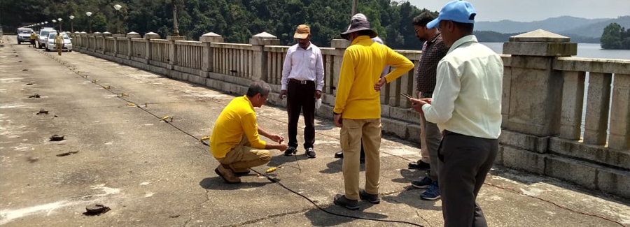
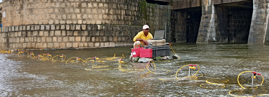
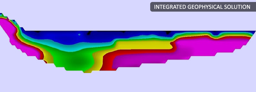
2D Resistivity Imaging uses an array of electrodes (typically 64) connected by multicore cable to provide a linear depth profile, or pseudosection, of the variation in resistivity both along the survey line and with depth. Switching of the current and potential electrode pairs is done automatically using a laptop computer and relay box. The computer initially keeps the spacing between the electrodes fixed and moves the pairs along the line until the last electrode is reached. The spacing is then increased and the process repeated in order to provide an increased depth of investigation.  Â
Â
Applications:
|
Advantages:
|
Â
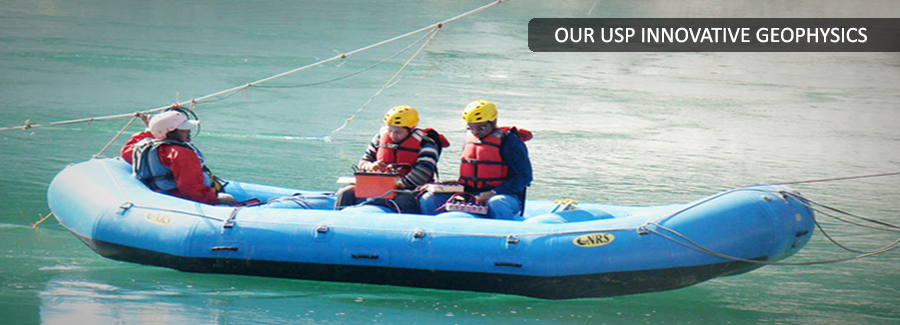
The technique is extremely useful for investigations of important sites to get information on weak zones or buried channels, under the rock interface, which goes undetected in seismic refraction, which terminated at rock interface. Resistivity imaging can also be effectively used to determine rock profile along dam axis across high current shallow rivers where deployment of hydrophones is not possible restricting use of seismic refraction. For deep penetration seismic refraction techniques requires use of explosives, which are not always feasible to deploy especially in sensitive areas. In such cases resistivity imaging can be effectively used to get detailed information of deeper layers.
Â
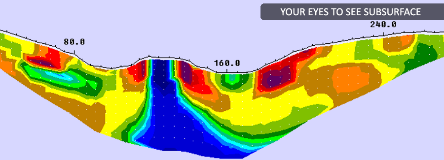
Following are examples from work of resistivity imaging carried out by PARSAN at HEP sites.
Â
Â
Â
ReMi (Refraction Micro-tremor)
Â
PARSAN also has launched for the first time in India, innovative technique of ReMi (Refraction Micro-tremor) having distinct edge over MASW and SASW in terms of logistics, execution and results. ReMi can be performed under the same layout as used for seismic refraction, to obtain excellent shear wave velocity profiles of subsurface. ReMi is a new, proven seismic method for measuring in-situ shear-wave (S-wave) velocity profiles. It is economic both in terms of cost and time. Testing is performed at the surface using the same conventional seismograph and vertical P-wave geophones used for refraction studies. Depending on the material properties of the subsurface, ReMi can determine shear wave velocities down to a minimum of 40 meters (130 feet) and a maximum of 100 meters (300 feet) depth.
Â
Â
Key Benefits. The ReMi method offers significant advantages. In contrast to borehole measurements. ReMi tests a much larger volume of the subsurface. The results represent the average shear wave velocity over distances as far as 200 meters (600 feet). Because ReMi is non-invasive and nondestructive, and uses only ambient noise as a seismic source, no permits are required for its use. ReMi seismic lines can be deployed within road medians, at active construction sites, or along highways, without having to disturb work or traffic flow. Unlike other seismic methods for determining shear wave velocity, ReMi will use these ongoing activities as seismic sources. There is no need to close a street or shut down work for the purpose of data acquisition. And a ReMi survey usually takes less than two hours, from setup through breakdown. These advantages sum to substantial savings in time and cost. Moreover the method provides more accurate results compared to conventional effort of picking up shear waves from records which more often than not lead to errors.Â
Â
Crosshole/ downhole/ uphole Surveys:
The primary purpose of obtaining crosshole data is to obtain the most detailed in situ seismic wave velocity profile for site-specific investigations and material Characterization. Crosshole velocity data are valuable for assessing man-made materials, soil deposits, or rock formations. Â
The seismic technique determines the compressional (P-) and/or shear (S-) wave velocity of materials at depths of engineering and environmental concern where the data can be used in problems related to soil mechanics, rock mechanics, foundation studies, and earthquake engineering. Â
Â
Features:
-
Precise determination of P and S wave seismic velocities.
Â
Advantages:
-
Determination of Dynamic Elastic Moduli like Poisson’s Ration, Young’s Modulus, Shear Modulus.
-
Detects even thin anomalous zones in subsurface.
Â
Limitations:
-
Good borehole preparation criticalÂ
-
Borehole verticality/ inclination to be ascertained.
Â
PARSAN also carried out downhole and uphole surveys, which work on the similar principle as explained in this section, with minor differences in data acquisition methodology.
Â
Ground Penetrating Radar
Â
Ground Penetrating Radar, also known as GPR, Georadar, Subsurface Interface Radar, Geoprobing Radar, is a totally non-destructive technique to produce a cross section profile of subsurface without any drilling, trenching or ground disturbances. Ground penetrating radar (GPR) profiles are used for evaluating the location and depth of buried objects and to investigate the presence and continuity of natural subsurface conditions and features
Â
Application Areas:
Â
-
Geological and hydro-geological investigations including mapping of bedrock topography, water levels, solution features, glacial structures, soils and aggregates.
-
Engineering investigations to evaluate dams, sea walls, tunnels, pavements, roadbeds, railway embankments, piles, bridge decks, river scour, buildings and monuments.
-
Location and evaluation of buried structures including utilities, foundations, reinforcing bars, cavities, tombs, archaeological artifacts, and animal burrows.
-
Site investigations: location of buried engineering structures and underground storage tanks.
-
Subsurface mapping for cables, pipes and other buried structures prior to trench-less operations.
Â
Advantages:
-
Rapid ground coverage- Antenna towed either by hand or from a vehicle.
-
High-resolution coverage of the survey area, detecting even small objects.
-
On-site interpretation possible due to instant graphic display.
Limitations:
-
Data acquisition may be slow over difficult terrain.Â
-
Depth of penetration is limited in materials with high electrical conductivities, clays.
-
Energy may be reflected and recorded from aboveground features, walls, canopies, unless antennae are well shielded.
-
Artifacts in the near surface (reinforcing bars, boulders, components of made ground) may scatter the transmitted energy and complicate the received signal and/or reduce depth of penetration.
-
Working on principle of reflection, GPR detects the utilities and provides information on depth and location. Classification of utility any further can be done only with availability of background data and is not a deliverable of GPR survey.
Induction Locator- Detection of Live Power Cables & Telecom cables:
Radio-detection uses the principles of electromagnetic to detect underground utilities. This principle works on the basis that a current flowing along a conductor creates a magnetic field, which extends around the conductor in concentric circles. A receiver coil can be used to detect the amplitude of this magnetic field. The amplitude varies depending on the position and orientation of the receiver within the field. The amplitude is maximum when the receiver is in line with the field and directly above the conductor. Moving the receiver from side to side it is possible to follow the maximum signal response and, therefore, the line of the buried service.Â
Â
Â
Both active and passive methods are used to ensure all possible detectable services are located.
Active Methods
An active signal is a signal that has been artificially generated by an external source. Active radiodetection methods can allow different services such as BT and electric to be individually identified. Active methods involve the use of a transmitter. The transmitter can either be used for direct connection or for induction. Direct connection involves the application of an active signal to a conductor using a clamp. Induction involves a signal being radiated from the internal antenna of the transmitter, which is induced to any conductors in the vicinity and re-radiated. Generally 8, 33 or 65KHz frequencies are used. It is often possible to determine the depth of the service in this mode.
Passive Methods
A passive signal is a signal that occurs 'naturally' on a buried conductor. Passive radio detection methods will provide an indication only that services are present underground. Passive methods use the electro-magnetic fields already present around the underground utility to locate them.
Two modes are generally used:
Â
-
Power -detects 50-60Hz energy present on most buried conductors
-
Radio -detects re-radiated radio energy often present on conductors -it is not possible to determine depth in this mode.
Â
The radio-detection method, coupled with GPR, provides excellent data on underground utility network.
Micro Gravity Surveys:
Gravimetry is a potential field technique which measures variations in the Earth's gravitational field. These variations are caused by density contrasts in the near surface rock and sediment. Gravimetric surveys are carried out using extremely sensitive instruments capable of measuring tiny variations in the gravitational field. These surveys are always carried out in conjunction with a precise topographic survey, to enable terrain corrections to be carried out.
Typical applications are:
-
Regional geological mapping;
-
Oil and gas exploration;
-
Mineral exploration;
-
Sediment thickness studies;
-
Archaeological surveys;
-
Void detection.
The technique is extensively used for cavity detection, along with other techniques of electrical imaging, GPR etc.Â
Â
Scintrex CG-5 gravimeter
Â
Gravity measurements define anomalous density within the Earth; in most cases, ground-based gravimeters are used to precisely measure variations in the gravity field at different points. Gravity anomalies are computed by subtracting a regional field from the measured field, which result in gravitational anomalies that correlate with source body density variations. Positive gravity anomalies are associated with shallow high density bodies, whereas gravity lows are associated with shallow low density bodies. Thus, cavities and voids can be readily detected using micro-gravity surveys.Â