
Blog
Standardizing Subsurface Utility Engineering (Detection & Mapping of Existing Utilities)
Standardizing Subsurface Utility Engineering (Detection & Mapping of Existing Utilities)
Dr. Sanjay Rana, Director, PARSAN Overseas Pvt. Ltd.
New Delhi, India, sanjay@parsan.biz
Abstract
Various utility installation projects involve execution using a mix of cable laying technologies like HDD (Horizontal Directional Drilling), MT (Micro-Trenching) and open trenching. Infrastructure projects also require accurate information on underground utilities in planning and construction stages.
To be able to avoid damages to existing utilities, especially in Indian cities with extreme subsurface utilities congestion, record creation of existing subsurface utilities is the first step. Well accepted process of SUE (subsurface utility engineering) can be adopted for collection and depiction of existing subsurface utility data.
Subsurface Utility Engineering (SUE) is a discipline dedicated to the determination of the exact location of existing underground facilities. Use of SUE makes sure that utilities are accurately picked up and plotted on site plans. This in turn reduces costs, delays, and public inconvenience. In addition, by eliminating the risk of utility breakage, the project will be safer for both construction personnel and the general public, hence reducing liability concerns. Subsurface Utility Engineering, or SUE is a new discipline that utilizes modern techniques to detect underground utilities in a total non-destructive manner. This process results in a digital map that will identify utilities within the project area. Assigning quality attributes to subsurface utilities is a key component of SUE process that denotes the quality of that utility information. Code of Practice for Collection and Depiction of Underground Utility Data Suiting Indian Conditions is presently under preparation.
The unique nature of utilities and record keeping in India necessitate various changes in SUE approach, and present paper discusses such procedures. This information can guide such projects in future.
INTRODUCTION
The nation’s infrastructure continues to grow as a result of population growth and other factors. New technologies are proliferating, such as fibre-optics (OFC), which are replacing copper communication cables. In addition, the deterioration and replacement of existing structures have expanded activities dealing with the utility infrastructure. The effort to clean up the environment has necessitated considerable excavation in areas of high-density infrastructure development. Available right-of-way is becoming limited, especially in urban and suburban areas. The “footprint” of new construction, repair, or remediation often conflicts with existing infrastructure. When this existing infrastructure is hidden from view (e.g., buried), it is often discovered in the construction phase of a project. During this phase, the costs of conflict resolution and the potential for catastrophic damages are highest.
Existing subsurface utilities and their related structures constitute a significant portion of this infrastructure. They create risks on projects. Inaccurate, incomplete, and/or out-of-date information on the existence and location of existing subsurface utilities reduces the engineers’, owners’, and contractors’ abilities to make informed decisions and to support risk management decisions regarding the project’s impact on existing utilities.
A convergence of new equipment and data-processing technologies now allows for the cost-effective collection, depiction, and management of existing utility information. These technologies encompass surface geophysics, surveying techniques, computer-aided design and drafting and geographic information systems, and minimally intrusive excavation techniques. This convergence of technologies and systematic use of the data derived from these technologies is known as subsurface utility engineering (SUE). Organizations across the world including utility companies are endorsing the use of SUE.
The engineer’s job in collecting and depicting utility information is complicated by the relatively limited control over utility owners’ record data. The utility owner is typically under no obligation to the engineer to provide information. The engineer is therefore often unable to obtain available and pertinent utility information.
For reliable information during design and construction, the engineer, owner, and constructor should be certain that utilities, active, abandoned, or unknown, are identified; that the utilities are marked correctly; that the numbers of actual utility pipes or cables under the ground are known or represented by multiple marks; that the width of facilities is correct; and that the depths of utilities are known. Reliable information has historically not always been provided by utility owners.
Engineers may have received, made, or obtained a mixture of evidence of the existence, character, and location of utilities. Evidence may vary widely as to its credibility. Application of a guideline like ASCE 38-02 and the establishment of a credible nomenclature system will permit affixing attributes to utility information that denote the quality of that utility information. Problems with existing utilities are routinely handled through change orders, extra work orders, insurance payouts, and contingency pricing. When problems create significant costs, the finger of blame is pointed everywhere, including at the engineer who has affixed his or her stamp to the plans, regardless of disclaimers. All involved in the design and construction process will benefit from better information for the management of risk.
SUBSURFACE UTILITY ENGINEERING
Most of Indian cities have an extremely complex network of utilities, typically characteristic of a developing country. The records on existing utilities underground are either simply non-existent or inaccurate. Various construction and planning projects require accurate information on underground utilities. Accurate techniques for non-destructive detection of such utilities, therefore, are extremely important. Poor records, improper notification, and excavation errors all contribute to making subsurface utility breaks an often costly but preventable problem. Subsurface Utility Engineering (SUE) is a discipline dedicated to the determination of the exact location of existing underground facilities. Use of SUE makes sure that utilities are accurately picked up and plotted on site plans. This in turn reduces costs, delays, and public inconvenience. In addition, by eliminating the risk of utility breakage, the project will be safer for both construction personnel and the general public, hence reducing liability concerns. Subsurface Utility Engineering or SUE is a new discipline that utilizes modern techniques to detect underground utilities in a total non-destructive manner. This process results in a digital map that will identify utilities within the project area.
Information obtained from other sources such as municipalities, is rarely accurate enough for project planning and execution. In addition, depth information is almost never available. Most of the information on past utilities has never been documented in systematic manner. SUE contractors on the other hand gather the primary data, and prepare an accurate and precise location map. This not only provides great insight to the subsurface conditions, but eliminates the unknown variables and contingencies designers face every day.
The procedure involved in data collection for existing utilities consists of various steps, starting from quick reconnaissance to detailed investigations. Various techniques used are:
Historical Utility Records Research
The data collection under this stage is aimed at obtaining basic information on possible locations, congestion and orientation of utilities. Such information is highly inadequate for use by construction contractor, but immensely useful for SUE contractor to plan density and orientation of survey lines, choose the right equipment, and plan the survey operations.
Designation
Designation is the process whereby the approximate horizontal location of a utility is determined. Following a rough approximation of the general location of facilities provided by Historical records research and visual site assessment, a number of geophysical technologies can be used, selected by applicability, for identifying the horizontal locations of particular utilities.
Induction Utility Locators
Induction utility locators operate by locating either a background signal or by locating a signal introduced into the utility line using a transmitter. There are three sources of background signals that can be located. A utility line can act like a radio antenna, transmitting electromagnetic signals that can be picked up with a receiver. AC power lines have a 50HZ signal associated with them. This signal occurs in all active AC power lines regardless of voltage. Utilities in close proximity to AC power lines or used as grounds may also have a 50HZ signal that can be located with a receiver. A signal can be indirectly induced onto a utility line by placing the transmitter above the line. Through a process of trial and error, the exact above position can be determined. A direct induced signal can be generated using an induction clamp. The inductor clamp induces a signal on specific utilities. This is the preferred method of tracing, where possible. By virtue of the closed loop, there is little chance of interference with the resulting signals. When access can be gained to a conduit, a flexible insulated trace wire can be used. The resulting signal loop can be traced. This is very useful for non-metallic conduits. Finally, these signals can be located horizontally on the surface using a receiver. The receiver is moved across the estimated location of the utility line until the highest signal strength is achieved. This is the approximate horizontal location of the utility. The receiver is then rotated until minimal signal strength is achieved. This will give the approximate orientation of the utility. Vertical depth, however, derived from this equipment is subject to gross error.
Magnetic Locators
Ferrous Metal or Magnetic locators operate by indicating the relative amounts of buried ferrous metals. They have limited application to locating and identifying utility lines but can be very useful for locating underground storage tanks (UST's) and buried manhole covers or other subsurface objects with a large ferrous metal content.
Electromagnetic Surveys
Electromagnetic survey equipment is used to locate metallic utilities. This method pulses the ground and records the signal retransmitted back to the unit from subsurface metal. Particularly useful for locating metal pipelines and conduit, this device also can help locate other subsurface objects such as UST’s, buried foundations (that contain structural steel), and pilings and pile caps (that also contain steel).
Ground Penetrating Radar
Ground Penetrating Radar (GPR) is an electromagnetic method that detects interfaces between subsurface materials with differing dielectric constants (a term that describes an electrical parameter of a material). The GPR system consists of an antenna, which houses the transmitter and receiver; and a profiling recorder, which processes the received signal and produces a graphic display of the data. The transmitter radiates repetitive short-duration EM signals into the earth from an antenna moving across the ground surface. Electromagnetic waves are reflected back to the receiver by interfaces between materials with differing dielectric constants. The intensity of the reflected signal is a function of the contrast in the dielectric constant at the interface, the conductivity of the material, which the wave is traveling through, and the frequency of the signal. Subsurface features which may cause such reflections are: 1) natural geologic conditions such as changes in sediment composition, bedding and cementation horizons, voids, and water content; or 2) man-introduced materials or changes to the subsurface such as soil backfill, buried debris, tanks, pipelines, and utilities. The profiling recorder receives the signal from the antennae and produces a continuous cross section of the subsurface interface reflections, referred to as reflectors.
Depth of investigation of the GPR signal is highly site specific, and is limited by signal attenuation (absorption) of the subsurface materials. Signal attenuation is dependent upon the electrical conductivity of the subsurface materials. Signal attenuation is greatest in materials with relatively high electrical conductivity such as clays and brackish groundwater, and lowest in relatively low conductivity materials such as unsaturated sand or rock. Maximum depth of investigation is also dependent on antennae frequency and generally increases with decreasing frequency; however, the ability to identify smaller features is diminished as frequency decreases.
The various GPR antennas used are internally shielded from aboveground interference sources. Accordingly, the GPR signal is minimally affected by nearby aboveground conductive objects such as metal fences, overhead power lines, and vehicles.
A GPR survey is performed by towing an antenna across the ground along predetermined transect lines. The antennae is either pulled by a person or towed behind a vehicle. Preliminary GPR transects are performed over random areas of the site to calibrate the GPR equipment and characterize overall site conditions. The optimum time range settings are selected to provide the best combination of depth of investigation and data resolution for the subsurface conditions at the site. Ideally, the survey is performed along a pre-selected system of perpendicular or parallel transects lines. The configuration of the transect lines is designed based on the geometry and size of the target and the dimensions of the site. The beginning and ending points of the transect lines and grid intersection points, or nodes, are marked on the ground with spray paint or survey flags. A grid system is used to increase the probability of crossing the short axis of a target providing a more definitive signature in the data. The location of the antenna along a transect line is electronically marked on the cross section at each grid intersection point to allow correlation of the data to actual ground locations. The location of the targets can be marked on the ground surface using spray paint or survey flags.
Acoustic Location Methods
Acoustic location methods generally apply to waterlines. A highly sensitive Acoustic Receiver listens for background sounds of water flowing; (at joints, leaks, etc.) or to sounds introduced into the water main using a transducer. This method may have good identification results, but can be inaccurate. Acoustics can also being utilized to determine the location of plastic gas lines.
Exposing the Utility via minimally intrusive excavation
This information provides the highest level of accuracy presently available. It involves “locating”; the use of non-destructive digging equipment to expose buried utilities at critical points. When surveyed and mapped, precise plan and profile information is available for use in making final design decisions. The use of non-destructive digging equipment, particularly vacuum excavation, eliminates damage to underground utility facilities traditionally caused by backhoes. By knowing exactly where a utility is positioned in three dimensions, the designer can often make small adjustments in design elevations or horizontal locations and avoid the need to relocate utilities. Additional information, such as the composition, condition, and size of the underground utility, soil contamination, pavement thickness, etc., also assist the designer and the utility owner in making important decisions.
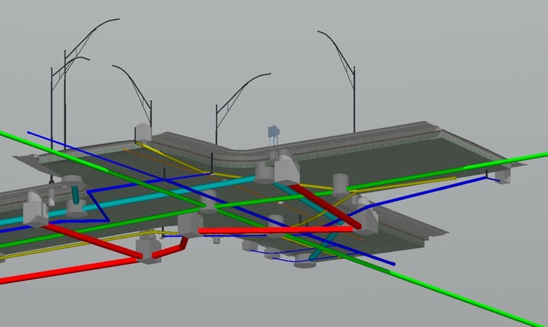
Data Management
Equipped with this EXACT information, the Data Management aspect of SUE can begin. These four categories of invaluable information can be utilized to provide extremely accurate subsurface "photographs" for designers. The unique blending of all four of these distinct procedures produces the most exact CADD map possible. After concluding the locating stage, the exact utility data is then translated into a computer generated maps. This computer-generated map then becomes a critical weapon for the designer, allowing for exact instructions to be crafted for excavation. The sum total of benefits to the client when SUE is utilized is the virtual elimination of utility breaks and work stoppages, cost overruns, safety hazards, adverse publicity, and the ensured health and safety of the general public all related to subsurface utility breaks.
When all of these procedures are blended together and applied, a clear and exact visual representation of the position of underground utilities in an area of excavation is produced. Each of these tools, applied independently, offers a limited and only partial representation of the subsurface utilities. The benefits derived from the application of these procedures are maximized when each is fully utilized to complement one another.
The two-fold end result of performing a complete SUE survey is:
· A precise subsurface map that almost eliminates utility breaks, safety hazards or claims, and public outcry, and
· Confidence to provide the client or owner with the best product while reducing design cost and compressing schedules.
SUE Deliverables
One of the major features of SUE is to assign quality levels to the utility information. QL A indicates the precise horizontal and vertical location of utilities obtained by the actual exposure (or verification of previously exposed and surveyed utilities) and subsequent measurement of subsurface utilities, usually at a specific point. QL B indicates information obtained through the application of appropriate surface geophysical methods to determine the existence and approximate horizontal position of subsurface utilities. QL C indicates information obtained by surveying and plotting visible above-ground utility features and by using professional judgment in correlating such information to QL D information. QL D indicates information derived from existing records and oral recollections.
The deliverables by SUE follow standard formats, developed by SUE consultant in consultation with the client. The scope includes:
· Decide on standard format, symbols, line types, code and attributes
· Mark quality level attribute to each line segment
· Present data as Plan sheet
· Decide on Line code and style, Labeling, Symbol embedding, Color, Line weight, Layers, Text
The standard format of delivery enables management of large amount of data in geographical reference system, which can be merged, edited and updated as new data becomes available from time to time.
UTILITY QUALITY LEVEL ATTRIBUTES
Utility quality level is a professional opinion of the quality and reliability of utility information. Such reliability is determined by the means and methods of the professional. Each of the four existing utility data quality levels is established by different methods of data collection and interpretation.
Utility quality level A
Precise horizontal and vertical location of utilities obtained by the actual exposure (or verification of previously exposed and surveyed utilities) and subsequent measurement of subsurface utilities, usually at a specific point. Minimally intrusive excavation equipment is typically used to minimize the potential for utility damage. A precise horizontal and vertical location, as well as other utility attributes, is shown on plan documents. Accuracy is typically set to 15-mm vertical and to applicable horizontal survey and mapping accuracy as defined or expected by the project owner.
Utility quality level B
Information obtained through the application of appropriate surface geophysical methods to determine the existence and approximate horizontal position of subsurface utilities. Quality level B data should be reproducible by surface geophysics at any point of their depiction. This information is surveyed to applicable tolerances defined by the project and reduced onto plan documents.
Utility quality level C
Information obtained by surveying and plotting visible above-ground utility features and by using professional judgment in correlating this information to quality level D information.
Utility quality level D
Information derived from existing records or oral recollections.
STANDARD PROCESS SUITING INDIAN CONDITIONS
1. The land survey part of preparing base maps and marking position of surface appurtenances can be done using widely available equipment Total Station. Few coordinates, however, must be picked up using DGPS to have maps and findings in standard coordinate system. The levels also must be correlated to MSL, enabling denoting RL of utilities. This will ensure an accurate positioning information availability even in future once surface elevation has undergone a change (due to addition of a new layer on road surface etc.)
2. For underground detection of utilities, ground penetrating radar and induction locators must be used together on all the projects. Acoustic based location systems can be used to detect small non-metallic house connections which are difficult to be picked by GPR due to their small size and material properties. It is observed that GPR frequencies in the range of 100 to 500 MHz are adequate for detection of most utilities.
3. Heavy congestion of utilities renders passive mode of induction locators ineffective in most city conditions. Active mode with direct coupling (for telecom lines, wherever possible), and loop based inductive coupling (for electric cables) should be deployed, with appropriate frequency.
4. Most of the projects does not allow enough time to open pits for quality level A measurements. Existing chambers and manholes should therefore be opened to inspect utilities and treated as QL-A measurements.
CONCLUSIONS
SUE is no longer a novelty. SUE is now recognized by the American Society of Civil Engineers (ASCE) as a viable and necessary component for the practice of civil engineering. Their national standard CI/ASCE 38-02, Standard Guidelines for the Collection and Depiction of Existing Subsurface Utility Data, has major ramifications regarding the allocation of risk for utility owners, constructors, and engineers. SUE is now considered a necessary process for every project designed by a civil engineer. The result will be that the reliability of utility data on plans is better defined. Code of Practice for Collection and Depiction of Underground Utility Data Suiting Indian Conditions is presently under preparation.
.jpg)